DC2 IBRA-type discretizations in computational solid mechanics:
COMPARISON OF IGA & FEM IN COMPUTATIONAL SOLID MECHANICS
In the field of computational solid mechanics, the prediction of mechanical behavior and damage evolution in materials is a critical challenge. Among the most widely used numerical techniques for solving solid mechanics problems, Isogeometric Analysis (IGA) and Finite Element Method (FEM) stand out due to their ability to model complex material behaviors, including damage, cracks, and deformations. This chapter provides an in-depth comparison of IGA and FEM in the context of computational solid mechanics, focusing on damage mechanics and the ability to simulate material failure and crack propagation.
1 Introduction to Isogeometric Analysis and Finite Element Method
Isogeometric Analysis (IGA), introduced by Hughes et al. (2005), integrates Computer-Aided Design (CAD) representations directly into the analysis process, enabling a seamless representation of geometry and the solution fields. The basis of IGA is the use of Non-Uniform Rational B-Splines (NURBS) or B-splines for both the geometry and the solution field (e.g., displacements, stress, etc.). This exact representation of geometry provides significant advantages over traditional finite element methods.
The Finite Element Method (FEM), on the other hand, has been the standard numerical method for solving solid mechanics problems for decades. FEM discretizes the domain into small elements, where the problem is solved numerically using polynomial approximations. While FEM has proven to be highly versatile and effective in a wide range of problems, it typically involves approximations of the geometry, leading to potential errors, especially in complex structures.
Both methods are widely used in computational solid mechanics, including in the study of damage mechanics, where the goal is to predict the evolution of damage in materials under various loading conditions. However, their differences in geometry representation, element formulation, and crack modeling make them suitable for different types of damage problems.
2 Geometry Representation and Continuity
- Isogeometric Analysis (IGA): A key feature of IGA is its exact representation of geometry. Using NURBS or B-splines, IGA can represent curved and complex geometries exactly without the approximation errors seen in FEM. This is particularly beneficial when modeling intricate geometries, such as those encountered in damage mechanics simulations involving cracks or material interfaces. IGA also provides higher-order continuity (C1, C2, etc.) in its shape functions, making it ideal for simulating smooth deformation and material behavior.
- Finite Element Method (FEM): FEM approximates geometry using a discretized mesh, which can lead to errors when modeling complex geometries. The accuracy of the geometry representation in FEM depends on the mesh resolution and element type used. FEM typically employs lower-order continuity (C^0), meaning that while displacement continuity is maintained, higher-order derivatives such as stress and strain may exhibit discontinuities. This lower continuity can be a limitation when dealing with smooth material behavior but is suitable for handling discontinuous damage such as cracks.
- Comparison: While IGA provides a more accurate and continuous representation of the geometry, FEM is more flexible in handling different types of element formulations, which makes it more adaptable to problems involving localized damage and cracks.
3 Element Design and Mesh Sensitivity
- Isogeometric Analysis (IGA): IGA uses higher-order elements that are capable of capturing complex material behavior with fewer degrees of freedom compared to FEM. The higher-order basis functions in IGA provide better accuracy for problems involving smooth deformations and damage evolution. In many cases, IGA requires fewer elements to achieve the same level of accuracy, especially for problems involving complex geometries.
- Finite Element Method (FEM): FEM typically uses lower-order elements that require finer meshing and local refinements to achieve the desired level of accuracy. In problems involving damage localization, such as crack propagation, fine mesh refinement near the crack tip is often necessary. Mesh sensitivity is a common issue in FEM, especially when dealing with stress concentrators or sharp damage features.
- Comparison: While IGA generally requires fewer elements for high accuracy in smooth problems, FEM’s flexible meshing and adaptive refinement capabilities make it better suited for problems involving sharp damage features, such as cracks, where localized refinement is needed.
4 Modeling Cracks and Damage Propagation
- Isogeometric Analysis (IGA) and Crack Propagation: A significant challenge in damage mechanics is simulating the propagation of cracks. IGA’s smooth basis functions are not naturally suited for capturing the discontinuities introduced by cracks, as they lead to sharp changes in displacement and stress fields. The inherent higher continuity of IGA can create difficulties in modeling crack initiation and propagation in a realistic manner, especially in mode I fracture where stress singularities are present.
- Approaches to Handle Cracks in IGA: To address this challenge, several strategies have been developed:
- Phase-Field Models: These models introduce a continuous representation of cracks, simulating crack growth as a gradual transition from intact to damaged material. Phase-field models are particularly well-suited to IGA, as they allow for the smooth evolution of damage without the need for sharp discontinuities (Miehe et al., 2010).
- Extended Finite Element Method (XFEM): XFEM can be combined with IGA to enrich the basis functions near the crack region, allowing for the representation of cracks without the need for remeshing (Belytschko et al., 2009).
- Approaches to Handle Cracks in IGA: To address this challenge, several strategies have been developed:
- Finite Element Method (FEM) and Crack Propagation: FEM, due to its lower continuity nature, is better suited for simulating cracks and discontinuous damage. FEM can easily accommodate cracks using various methods:
- Extended Finite Element Method (XFEM): XFEM extends the FEM by enriching the displacement field near crack regions to capture discontinuities in displacement and stress without the need for remeshing (Moës et al., 1999).
- Comparison: While IGA faces challenges in directly simulating cracks due to its smoothness and higher continuity, techniques like phase-field models, and XFEM allow IGA to simulate cracks effectively. On the other hand, FEM is naturally suited to handle discontinuous damage and crack propagation due to its ability to introduce sharp discontinuities and perform adaptive meshing.
5 Computational Efficiency
- Isogeometric Analysis (IGA): IGA’s exact representation of geometry and higher-order elements make it computationally efficient for problems with smooth damage evolution and complex geometries. The use of fewer elements can lead to significant computational savings. However, when applied to highly nonlinear damage models, the integration over higher-order elements can be computationally expensive (Hughes et al., 2005).
- Finite Element Method (FEM): FEM is highly adaptable and can be computationally efficient, especially when adaptive meshing or parallel processing techniques are used. However, problems involving cracks or localized damage often require fine mesh refinements, increasing computational cost. Remeshing during crack propagation can add further overhead (Zienkiewicz et al., 2005).
Comparison: IGA is more efficient for problems with smooth damage evolution and less complex crack behavior, while FEM is better suited for large-scale problems involving crack propagation and local damage.
ISOTROPIC DAMAGE MODELS
1 Isotropic Damage Models in One-Dimensional Systems
A critical area of study in damage mechanics is the development of isotropic damage models, which describe the degradation of material properties due to loading and unloading cycles. A commonly used formulation for such models is that introduced by Oliver et al. (Oli+90), which characterizes the stress-strain relationship of materials undergoing damage.
In the 1D isotropic damage model, the material response is governed by the evolution of a damage variable, which reduces the effective stiffness of the material as damage accumulates. This model accounts for both loading and unloading behavior, and its implementation involves solving the system of equations that govern the damage evolution process. For instance, by considering a material with properties such as Young’s modulus (E) of 1E+08 Pa, a yield stress of 2 MPa, and a fracture energy of 5E+04 J/m², the material’s degradation can be studied by solving the stress-strain relations for different loading paths, as illustrated by the stress-strain curve (Figure 3.1).
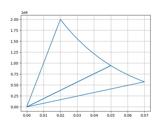
Figure 1. Stress-strain curve during both loading and unloading phases for the given material properties, with a Young’s modulus (E) of 1.00E+08 Pa, yield stress of 2.00E+06 Pa, and fracture energy of 5.00E+04 J/m2
2 Extension to Two-Dimensional Damage Models
Building on the 1D isotropic damage model, a natural progression is to extend the formulation to two-dimensional systems. In these models, the material exhibits strain-softening behavior, which requires careful attention to regularization techniques to prevent mesh dependence in simulations. The characteristic length (lc) is a critical parameter in this context, as it determines the scale at which damage is regularized, ensuring that damage and fracture processes are not overly influenced by the numerical mesh.
In traditional FEM formulations, the characteristic length is computed based on the maximum distance from the centroid of an element to its nodes. For a triangular element, the characteristic length lc is given by:
lc=max(∥𝐱c−𝐱i∥),i=1,2,3
where xc\mathbf{x}_c is the centroid and xi\mathbf{x}_i are the coordinates of the element’s vertices. This approach is effective in FEM, where the mesh is discretized with nodes. However, this definition is not directly applicable to Isogeometric Analysis (IGA), where elements are defined in terms of NURBS (Non-Uniform Rational B-Splines) basis functions rather than nodal points.
3 Characteristic Length in Isogeometric Analysis (IGA)
In IGA, the elements are not tied to a discrete mesh of nodes, but rather defined by the continuous nature of the NURBS basis functions. To maintain the role of the characteristic length in regularizing damage mechanics models within IGA, a new formulation is needed.
The characteristic length lc in IGA is defined based on the parametric spans of the NURBS basis functions, rather than relying on the geometry’s nodal discretization. For instance, for a quadrilateral element, the characteristic length can be expressed as:
lc=(॥𝐱(ui+1,vj)−𝐱(ui,vj)॥,॥𝐱(ui,vj+1)−𝐱(ui,vj)॥),
where 𝐱(u,v) is the mapping from the parametric space to the physical space, and uu and vv are the parameters defining the NURBS surface. This definition ensures that the characteristic length in IGA reflects the smooth, continuous nature of the geometry and maintains the regularization properties needed for accurate damage modeling.
4 Role of Regularization in Damage Mechanics
In damage mechanics, the regularization of strain-softening behavior is critical to obtaining stable and physically meaningful solutions. Without regularization, damage models can exhibit mesh dependence, where the results vary significantly with the mesh size, leading to unphysical crack patterns and non-converging solutions. The characteristic length lc, whether defined in FEM or IGA, serves as a scale factor that regularizes the damage evolution, ensuring that the results are independent of the discretization used.
The regularization process is particularly important in the simulation of fracture and material degradation, where local damage must be captured without introducing numerical artifacts. By defining lc in a way that is consistent with the underlying geometry, as in the case of the IGA-based definition, the approach mitigates mesh dependency and allows for more accurate simulations of complex material behavior.
Leave a Reply
Want to join the discussion?Feel free to contribute!