DC3 Application of IBRA-type discretizations in implicit contact mechanics:
Use of smooth CAD discretizations in contact mechanics is known to be beneficial.
A brief comparison: IGA and FEM
A key step in advancing the use of IGA was the implementation of a general body-fitted problem, where a flexible, nonlinear mapping between the parameter and physical spaces was developed. This mapping leverages IGA’s inherent capability to describe CAD geometries perfectly, ensuring precise simulation of even the most complex domains.
Advantages of IGA over FEM in Body-Fitted Scenarios
Comparative studies between IGA and FEM have revealed several advantages of IGA in body-fitted scenarios:
- Reduced Degrees of Freedom (DOFs):
IGA requires fewer DOFs to achieve the same error level compared to FEM. This is due to the higher-order continuity of NURBS, which reduces the number of elements and control points needed for accurate approximations. - Exact Geometry Representation:
Unlike FEM, where mesh generation can introduce geometric inaccuracies, IGA ensures that the computational domain is an exact replica of the CAD model (Figure 1). This exactness is particularly beneficial for problems where geometric fidelity is critical, such as those involving contact mechanics. - Simplified Refinement:
Refinement in IGA can be achieved without altering the underlying geometry, making it more straightforward to adapt the computational model to different levels of precision. - Higher Convergence Velocity:
Both FEM and IGA exhibit similar convergence orders when using the same polynomial degree. However, IGA’s ability to easily increase the order of basis functions without remeshing provides a significant edge. Higher-order basis functions lead to enhanced convergence rates, enabling IGA to achieve desired accuracy more efficiently and lower numbers of degrees of freedom (Figure 2).
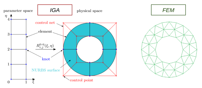
Figure 1: Comparison of IGA and FEM discretizations.
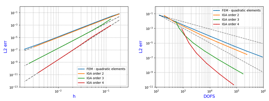
Figure 2: Comparison of IGA and FEM convergence and DOFs utilization.
The Shifted Boundary Method
The Shifted Boundary Method (SBM) offers a flexible framework to address challenges in numerical integration over complex domains, including contact mechanics. As outlined in, SBM shifts the imposition of boundary conditions from the true boundary Γ to a surrogate boundary h , composed of edges of a computational grid.
Boundary conditions are modified using Taylor expansions, ensuring optimal convergence rates. This approach avoids challenges associated with small cut cells and simplifies numerical integration, making it particularly suited for embedded methods and large deformation problems.
In this context, the SBM complements Isogeometric Analysis (IGA) by leveraging exact geometry descriptions and avoiding trimmed knot spans. This synergy improves the representation of physical geometries and enhances computational efficiency.
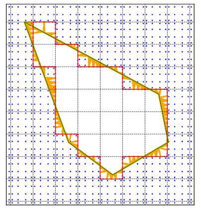
Figure 3: SBM main characteristics.
The SBM for IGA has been implemented inside the Kratos Multiphysics framework (KratosMultiphycsGithub) to handle 2D fluid and structural mechanics problems with complex geometries.
The SBM implementation preserves the optimal convergence of body-fitted cases under Dirichlet boundary conditions, though it experiences a one-order reduction in convergence for Neumann (load) conditions. This functionality has also been extended to 3D problems, broadening its applicability (Figure ).
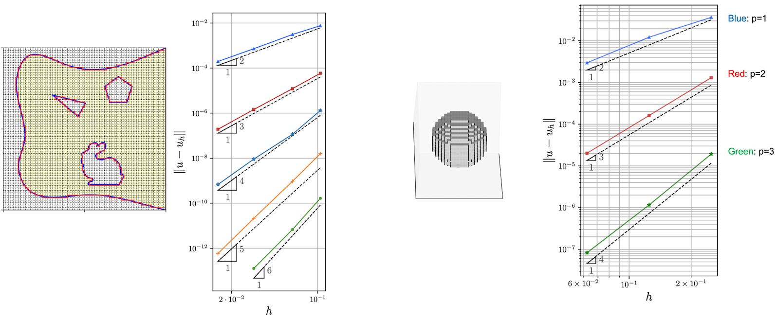
Figure 4: IGA+SBM for 2D/3D problems.
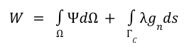
Finally, Figure 5 shows a convergence comparison between standard IGA and IGA with SBM for the case of circular geometry. No big loss is evident for the use of the SBM against the exact geometry of the body-fitted scenario.
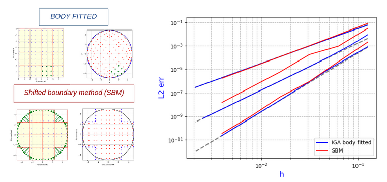
Figure 5. Comparison of IGA body-fiitted and IGA + SBM convergence for a circle.
Towards a “penalty-free” Contact mechanics
Contact mechanics investigates the interaction of surfaces under load, with emphasis on stress distribution, deformation, and phenomena such as friction and adhesion. This field is essential in various engineering applications, including mechanical systems, aerospace structures, and biomechanics, where precision is paramount for safety and performance.
- Governing equations and variational formulation
Contact mechanics deals with the study of stresses and deformations arising at the interface between contacting bodies. In computational mechanics, the weak form of the governing equations is often employed to facilitate numerical implementation.
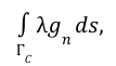
The formulation of contact mechanics begins with the total elastic potential energy of the system, expressed as:
where Ψ is the strain energy density, C denotes the contact interface, λ is the Lagrange multiplier associated with the contact stress, and g is the gap function, which measures the normal separation between contact surfaces.
By introducing the variation of the potential energy, the weak form of the contact problem becomes:
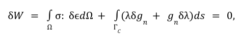
where σ is the Cauchy stress tensor, and ϵ is the strain tensor.
- Approaches to Enforcing Contact Constraints
Several methods have been developed to enforce contact constraints, each with its own advantages and limitations. Two of the most widely used are the Lagrange multiplier method and the penalty method, both of which are foundational to modern contact mechanics algorithms.
Lagrange Multiplier Method
The Lagrange multiplier method introduces an additional field, λ\lambdaλ, to explicitly enforce the contact constraints. The augmented variational form becomes:
where λ acts as a contact force. This approach ensures exact constraint satisfaction but increases the number of unknowns in the system. The method is robust but computationally expensive due to the saddle-point nature of the resulting system. Furthermore, poor conditioning of the system matrix can complicate numerical solution strategies.
Penalty Method
The penalty method simplifies the implementation by replacing the constraint with a penalty term in the variational form:
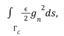
where ϵ > 0 is the penalty parameter. Larger values of ϵ enforce the constraints more strictly but can lead to numerical instability, while smaller values introduce constraint violations. Striking the right balance requires careful calibration, which can be problem-specific and nontrivial.
Nitsche’s “penalty free” Method
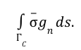
Nitsche’s method combines the strengths of both approaches by weakly enforcing contact constraints without introducing a Lagrange multiplier or requiring explicit penalty parameters. This formulation introduces stabilization terms that ensure numerical consistency and stability. The main idea is to substitute the lagrangian multiplier, , which physically represents the normal stress at the contact boundary, exactly with the stress at the contact, , that it’s directly computed from the displacements of the bodies involved in the contact and does not require additional degrees of freedom in the system. We can choose
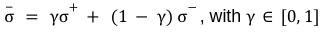
to set the contact stress closer to the master or slave contact stresses. In this way the perturbation to the potential results as
- Results
To validate the implementation, two classical benchmark problems and a case comparison with the classical Contact Lagrangian FEM were analyzed:
1. Patch Test
The patch test evaluates the ability of the algorithm to maintain stress and displacement continuity across a contact interface between two squares with non-coincident meshes. The Nitsche penalty-free formulation demonstrated excellent accuracy, achieving stress and displacement continuity within numerical tolerances. This result confirms the robustness of the nearest projection search and the contact activation/deactivation strategy.
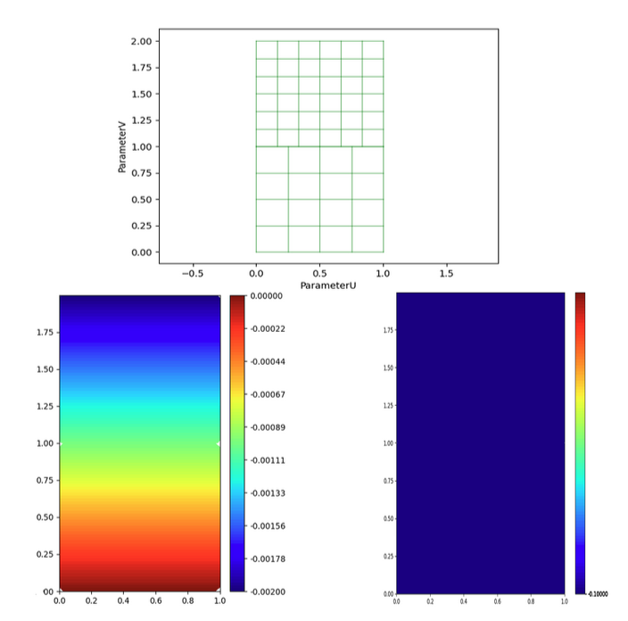
Figure 6: Patch test, Mesh (above), vertical-displacent (left ) vertical stress (right)
2. Hertz Contact Problem
The Hertz contact problem involves the interaction of a cylinder (or circle in 2D) with a rigid wall, serving as a well-known analytical reference for contact mechanics. The implementation accurately reproduces the contact pressure distribution, confirming the capability of the algorithm to capture normal stresses and displacements. In this case:
- The pressure distribution follows the classical parabolic shape, consistent with the analytical solution.
- The vertical displacement along the contact interface matches the derived theoretical solution, further validating the accuracy of the contact formulation.
These benchmarks highlight the robustness and accuracy of the contact algorithm, demonstrating its applicability to a wide range of contact problems, from simple linear cases to more complex non-linear scenarios. The results also underscore the advantages of the penalty-free Nitsche formulation in maintaining stability and avoiding the pitfalls associated with traditional penalty-based methods.
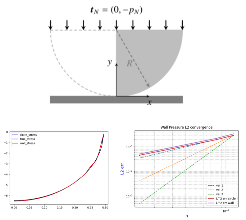
Figure 7: Hertz Circle-Wall contact, stress comparison with the true solution on the contact boundary.
3. Comparison with FEM
Finally a punch test has been checked against a well tested FEM contact solver with ALM. The penalty-free/IGA body fitted algorithm proves to converge fast the FEM accurate solution.
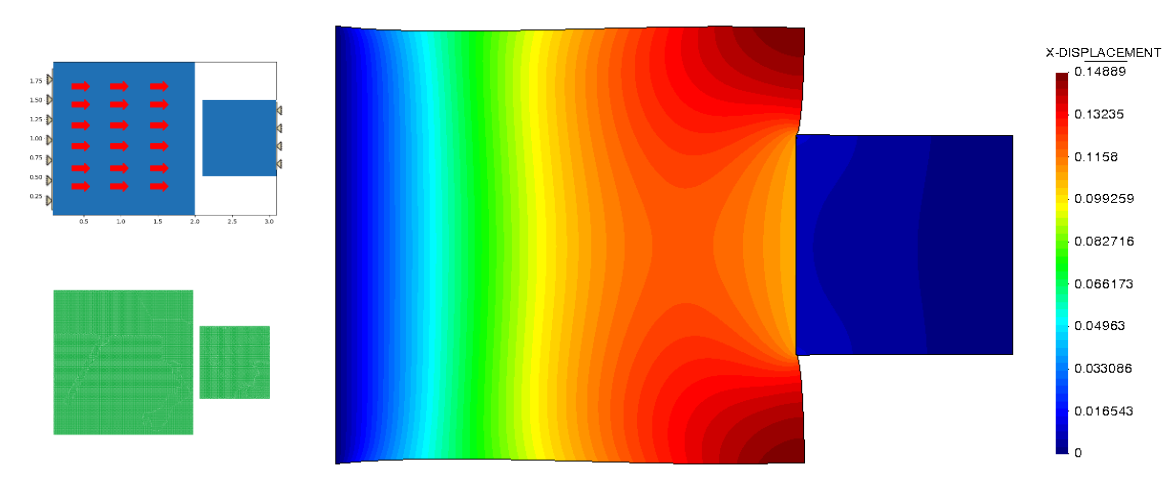
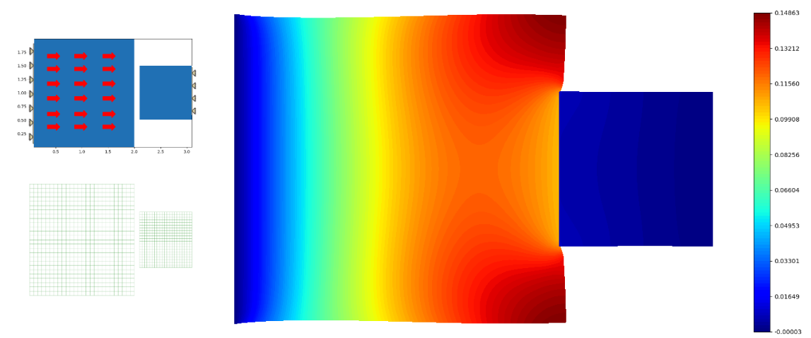
Figure 8:Punch test horizontal displacements, FEM (above) vs. IGA(below)
Leave a Reply
Want to join the discussion?Feel free to contribute!