
DC3 Application of IBRA-type discretizations in implicit contact mechanics:
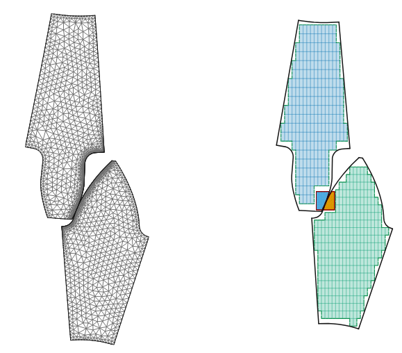
Isogeometric Analysis (IGA) has established itself as a powerful framework in computational mechanics by bridging the gap between Computer-Aided Design (CAD) and numerical simulation. By employing spline-based basis functions such as B-splines and NURBS, IGA enables exact geometry representation, high-order accuracy, and enhanced continuity across element interfaces, often achieving superior accuracy per degree of freedom compared with standard finite element discretizations. These properties are especially attractive in structural and contact mechanics, where geometric fidelity and smooth stress representation play a central role.
Despite these advantages, the practical use of boundary-fitted IGA remains challenging for complex geometries, trimmed models, and nonconforming interfaces. The generation of analysis-suitable parametrizations may require substantial preprocessing, while immersed and embedded approaches based on cut-cell integration are often affected by the small cut-cell problem, which can lead to poor conditioning and increased algorithmic complexity. Within this context, the Shifted Boundary Method (SBM) provides an attractive alternative by replacing the true boundary with a surrogate boundary aligned with the background mesh and transferring the boundary conditions through Taylor expansions. In this way, SBM avoids cut-cell integration, simplifies preprocessing, and preserves the favorable conditioning properties of the discretization. Its integration within IGA has therefore opened a promising route toward accurate and flexible high-order immersed simulations on complex domains.
The initial stage of this work focused on this integration of SBM within IGA and on its application to contact mechanics through a penalty-free Nitsche formulation. In the previous technical report, this framework was validated on classical benchmarks such as the patch test, the Hertz contact problem, and the punch test, showing that accurate and robust contact enforcement could be achieved without introducing Lagrange multipliers or penalty parameters. These results established the basis for extending the overall methodology toward immersed contact mechanics.
Since then, the project has evolved in two closely connected directions. On the one hand, in collaboration with Kangan Li and Guglielmo Scovazzi, an immersed SBM formulation for contact in linear elasticity has been developed and validated in the FEM setting [47], demonstrating that contact conditions can be imposed on surrogate contact surfaces while retaining robustness and avoiding cut-cell integration, even for complex and non-watertight geometries. On the other hand, the main methodological effort has shifted toward the development of the high-order isogeometric Gap–Shifted Boundary Method (Gap–SBM), introduced to overcome one of the main limitations of the classical SBM, namely the reduced accuracy in the treatment of Neumann boundary conditions. By explicitly accounting for the region between the surrogate and true boundaries through high-order Taylor extensions and gap integration, the Gap–SBM restores optimal convergence for both Dirichlet and Neumann conditions without adding degrees of freedom and while maintaining favorable numerical conditioning.
Within this same line of development, another contribution is a multipatch coupling strategy derived from the Gap–SBM framework. In the context of the present project, this should mainly be regarded as an enabling tool, since it allows nonconforming patches with different parametrizations, mesh sizes, and polynomial orders to be coupled in a robust way, while also making local refinement near critical regions significantly easier to introduce. This added flexibility is expected to play an important role in the next stages of the research, particularly for a more accurate comparison between classical SBM and Gap–SBM in immersed contact, and for future extensions to nonlinear material and plasticity.
The latest development of the project builds directly on these ingredients and applies them to immersed isogeometric contact mechanics. In this work, the SBM and Gap-SBM are used to formulate frictionless contact between independently immersed spline discretizations. Both formulations rely on the same biased one-pass Nitsche enforcement and mortar-type segmentation strategy, so that the role of the geometrical treatment of the contact interface can be assessed in a controlled way. The same framework also incorporates Gap-SBM multipatch coupling to introduce local h- and p-refinement in the vicinity of the contact zone, allowing high resolution to be concentrated only where it is needed.
- Background: The Shifted Boundary Method in Isogeometric Analysis
Isogeometric Analysis (IGA) has become an important framework in computational mechanics because it reduces the gap between Computer-Aided Design (CAD) and Computer-Aided Engineering (CAE). Initially introduced by Hughes et al. [1–5], IGA uses spline-based basis functions, such as B-splines and NURBS, to represent both the geometry and the unknown fields. This provides exact or highly accurate geometrical descriptions, high-order approximation, and enhanced continuity across element interfaces [6]. These properties are particularly attractive in structural and contact mechanics, where the accurate representation of boundaries, stresses, tractions, and contact quantities plays a central role.
Despite these advantages, the practical use of body-fitted IGA remains challenging for complex geometries. Industrial CAD models may contain trimmed surfaces, non-watertight interfaces, small geometrical features, or discontinuities that make the construction of analysis-suitable spline parametrizations difficult and time-consuming [12,13]. To overcome these limitations, several immersed and embedded approaches have been proposed, including the Finite Cell Method (FCM) [14,15] and Isogeometric Boundary Representation Analysis (IBRA) [16–20]. These methods relax the requirement of boundary-fitted discretizations by embedding the physical geometry in a background mesh. However, they usually require the integration of cut cells, which may lead to ill-conditioning when very small cut elements are present [21,22].
The Shifted Boundary Method (SBM) [23,24] provides an alternative immersed approach that avoids direct cut-cell integration. The main idea is to replace the true physical boundary with a nearby surrogate boundary aligned with the computational grid. Boundary conditions are then transferred from the true boundary to the surrogate boundary through Taylor-based shift operators. In this way, the method avoids arbitrarily small cut cells, simplifies numerical integration, and preserves favourable conditioning properties. Applications of SBM in the finite element setting have already demonstrated its effectiveness in solid mechanics, fluid mechanics, and related embedded-domain problems [25–28].
The integration of SBM within IGA was developed as a first step toward high-order immersed isogeometric simulations on complex geometries. In this setting, the smoothness and high-order derivatives available in spline spaces can be naturally exploited in the construction of the shifted boundary operators. The resulting SBM–IGA framework combines the geometrical and approximation advantages of IGA with the flexibility of immersed methods, allowing complex domains to be treated without body-fitted meshes or trimmed knot spans.
Figure 1 illustrates the basic idea of the SBM in the isogeometric setting. The physical boundary is represented together with the surrogate boundary, active background elements, boundary quadrature points, and projection vectors connecting the surrogate and true geometries. Boundary conditions are imposed on the surrogate boundary, while the information from the true boundary is recovered through the shift operators.
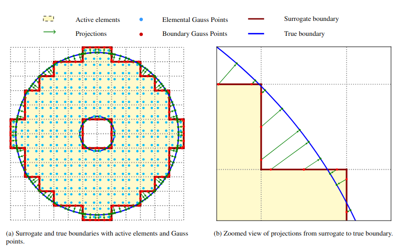
Figure 1: Main geometrical entities of the Shifted Boundary Method in the isogeometric setting.
The SBM–IGA implementation has been developed within the Kratos Multiphysics framework and applied to two- and three-dimensional structural mechanics problems with complex embedded geometries. The numerical results obtained in the first stage of the project showed that the method preserves the optimal convergence behaviour of body-fitted IGA for Dirichlet-dominated problems. In these cases, the shifted imposition of boundary conditions provides accurate results while retaining the conditioning advantages of a cut-cell-free discretization.
At the same time, these studies also revealed an important limitation of the classical SBM. While shifted Dirichlet boundary conditions are generally robust, Neumann and traction boundary conditions are more delicate, especially when high-order spline discretizations are used. In these cases, the shifted approximation of fluxes or stresses may lead to a reduction of accuracy and to sensitivity with respect to the position of the surrogate boundary. This issue is particularly relevant for structural and contact mechanics, where stresses, tractions, and contact pressures are primary quantities of interest.
Figure 2 shows a representative comparison between body-fitted IGA and SBM–IGA for a circular geometry. The results confirm that the SBM can reproduce the body-fitted behaviour with good accuracy, while avoiding the need for a conforming discretization of the physical boundary. The limitations observed for Neumann and traction-dominated problems motivated the subsequent development of the Gap-Shifted Boundary Method, which is discussed in the next section.
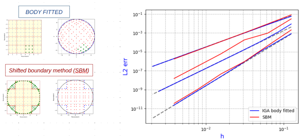
Figure 2. Comparison of IGA body-fitted and IGA + SBM convergence for a circle.
The same implementation was also tested on two- and three-dimensional embedded configurations, confirming that the SBM–IGA framework is not restricted to planar benchmark geometries (Fig. 3). These tests provided the basis for the later developments of Gap-SBM and immersed contact formulations.
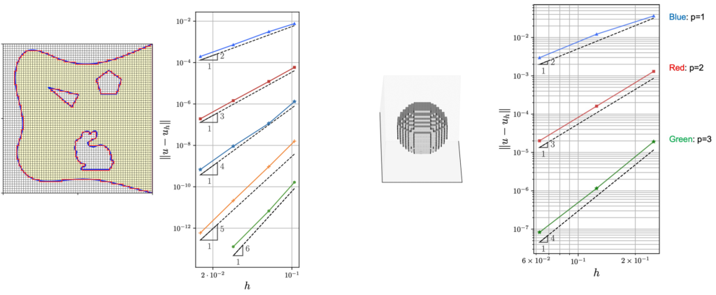
Figure 3. IGA+SBM for 2D/3D problems.
- The Shifted Boundary Method for contact problems
The first step toward immersed contact mechanics was developed in collaboration with Kangan Li and Guglielmo Scovazzi and is documented in [47]. This work introduced an embedded formulation for frictionless contact based on the Shifted Boundary Method. The main idea was to impose the contact conditions on a surrogate contact surface located close to the true physical contact boundary. Taylor-based shift operators were then used to transfer the relevant kinematic and mechanical quantities between the true and surrogate geometries.
This approach allowed contact constraints to be imposed without integrating the variational formulation over cut cells. As a consequence, the method avoided the small cut-cell instabilities that typically affect unfitted formulations, while retaining a contact treatment closely related to classical body-fitted methods. The formulation was developed for small-strain frictionless contact and was tested on Signorini-type and two-body contact problems in both two and three dimensions. The work was important for the overall project because it demonstrated that contact conditions can be transferred consistently from the true physical boundary to a surrogate boundary. In particular, it showed that the SBM can be used not only for standard boundary conditions, but also for unilateral contact constraints, where the active and inactive parts of the contact boundary are not known in advance and must be determined as part of the solution.
In the classical body-fitted Signorini setting, see Figure 4, the contact kinematics can be described through the normal gap between a point on the candidate contact boundary and its projection onto the obstacle. Under the small-strain assumption, the normal gap can be written as
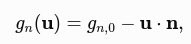
where gn,0 is the initial geometrical gap and n is the contact normal. Frictionless unilateral contact is then governed by the Hertz–Signorini–Moreau conditions

where pn is the normal contact pressure. These conditions express non-penetration, non-adhesion, and complementarity between the contact pressure and the normal gap.
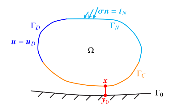
Figure 4. Signorini’s problem: the domain and the boundary partition = D U N U C , with D ∩ N = ∅, C ∩ N = ∅, and D ∩ C = ∅.

Where xC, d is the distance vector from the surrogate point to the corresponding true boundary point, and higher-order Taylor terms can be included depending on the approximation order. This shifted gap is the key ingredient that allows the contact conditions to be imposed on the surrogate boundary while accounting for the location of the true physical interface.
Higher-order Taylor terms can be included depending on the approximation order. The same idea is used to shift stress and traction quantities from the true contact boundary to the surrogate one. As a result, the active and inactive contact regions can be identified directly on the surrogate contact boundary, while still accounting for the location of the true physical interface.
The final contact formulation is obtained by combining this shifted description of the contact kinematics with a Nitsche-type weak enforcement of the contact traction. The Lagrange multiplier is used only as a conceptual bridge in the derivation; the final formulation is purely primal and does not introduce additional multiplier unknowns. This is an important practical advantage, since it avoids saddle-point systems while retaining a consistent weak enforcement of the unilateral contact conditions.
The resulting SBM contact formulation can therefore be interpreted as an immersed Nitsche-type contact method in which the contact gap, contact traction, and active-set criterion are shifted from the true boundary to the surrogate boundary. This allows the formulation to avoid cut-cell integration and to preserve the robustness of the shifted-boundary framework.
- Numerical validation of the FEM-SBM contact formulation
The formulation was first validated on a classical Hertzian disk-wall benchmark, in which an elastic half-disk comes into frictionless contact with a rigid horizontal wall. This benchmark is commonly used to assess contact formulations because it provides an analytical reference for the contact-pressure distribution. The geometry consists of a circular body of radius R=8 mm, and only half of the domain is modelled due to symmetry, as shown in Fig. 5. Two vertical traction levels were considered, pN=0.1 GPa and pN=0.3 GPa. The material parameters were set to E=200 GPa and =0.3. These are the same benchmark parameters described in the current report.
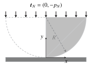
Figure 5. Two-dimensional Hertzian contact problem with circular boundary: geometry and setup.
The problem was solved using both a body-fitted reference discretization and the SBM contact formulation. The comparison showed that the SBM formulation was able to reproduce the body-fitted response with very good accuracy. Figure 6 evidentiates how the displacement components and the von Mises stress fields obtained with the two approaches were nearly indistinguishable, indicating that the shifted treatment of the contact boundary did not introduce visible distortions in the global deformation pattern or in the stress distribution.
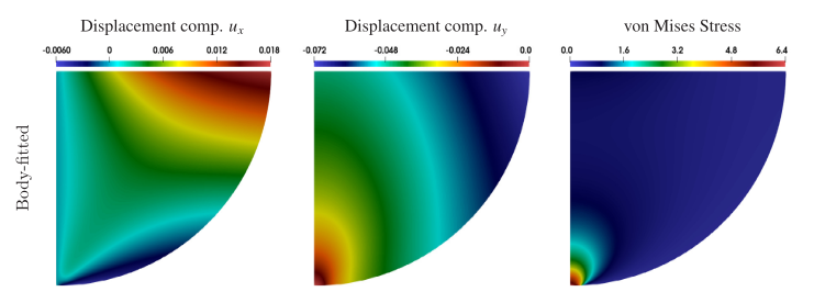
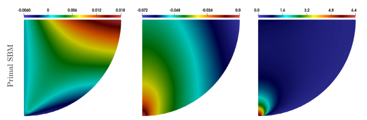
Figure 6. Two-dimensional Hertzian contact problem with circular boundary pN= 0.3 GPa: displacement components (x and y) and the von Mises stress with the body-fitted and SBM formulation.
A similarly good agreement is observed in the contact pressure distribution along the contact boundary (Fig. 7). The primal SBM results recover the classical Hertzian profile and converge to the analytical solution under mesh refinement, with an accuracy comparable to the body-fitted formulation. On the finest grids, the error in the maximum contact pressure remains below 1% for all formulations considered; more specifically, the body-fitted solution shows a slight overestimation, whereas the primal SBM produces a slight underestimation. Overall, these results show that the SBM formulation provides an accurate and robust immersed treatment of Hertzian contact, while retaining the main features of the body-fitted reference solution.
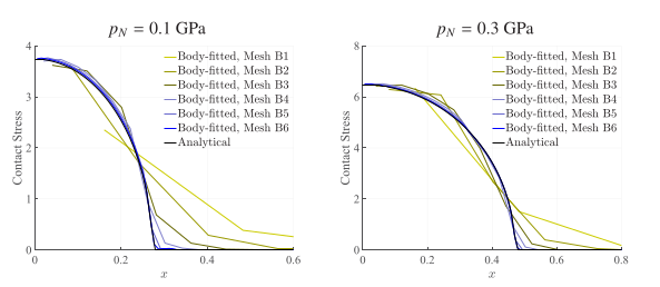
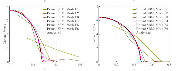
Figure 7. Two-dimensional Hertzian contact problem with circular boundary (for pN= 0.1 GPa and pN= 0.3 GPa): contact pressure along the boundary .
These results confirmed that the Shifted Boundary Method can provide an accurate and robust immersed treatment of frictionless contact while avoiding body-fitted mesh generation and cut-cell integration. The formulation was also extended to two-body contact problems and to three-dimensional configurations, showing the generality of the approach beyond the simple disk-wall benchmark. Nevertheless, this development was carried out in the finite element setting and effectively represents an intermediate step toward the high-order immersed isogeometric contact framework developed in the subsequent stages of the project.
- The Gap Shifted Boundary Method in IGA
This work [49] introduces a high-order isogeometric extension of the Gap-Shifted Boundary Method for linear elasticity. The method was developed to overcome one of the main limitations observed in the classical SBM, namely the reduced accuracy in the treatment of Neumann and traction boundary conditions on immersed geometries. While the standard SBM imposes boundary conditions on a surrogate boundary and accounts for the true boundary only through shifted quantities, the Gap-SBM explicitly reconstructs the geometrical region between the surrogate and physical boundaries.
The key idea is to extend the active spline approximation into this gap region by means of high-order Taylor expansions and to recover the missing contribution of the physical domain through curvilinear gap elements. These elements are introduced only for numerical integration and do not add extra degrees of freedom to the problem. As a result, the size of the algebraic system remains the same as in the classical SBM, while the weak form accounts more accurately for the true physical domain.
This construction preserves the main advantages of shifted-boundary methods, namely the avoidance of cut-cell integration and the favourable conditioning of the resulting linear systems. At the same time, it improves the accuracy of traction-dominated problems by reducing the sensitivity to the location of the surrogate boundary. The numerical results show that the Gap-SBM restores optimal convergence for both Dirichlet and Neumann boundary conditions and remains robust even for geometries with features smaller than the background mesh size.
Figures 7 and 8 illustrate the main geometrical and approximation ingredients of the method. Figure 7 shows the relation between adjacent gap elements, interface quadrature points, and the projection from the surrogate boundary. Figure 8 shows how the basis functions are extended from the surrogate domain to the interior of the gap elements and to the approximated physical boundary through Taylor expansions.
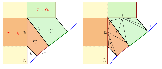
Figure 8. Left: Main geometric entities of two adjacent gap elements. Right: Quadrature points on the interfaces of the gap elements and their projection from the corresponding surrogate reference point. The arrows indicate the direction of the Taylor expansion used to extend the basis functions to the interface quadrature points.
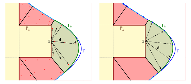
Figure 9. Left: Extension of basis functions used for integration over the interior of the gap element. Right: Extension of basis functions used for the integration of boundary condition terms on the approximated boundary. Arrows indicate the direction of the Taylor expansion used to evaluate the basis functions at interior and boundary quadrature points.
From a geometric point of view, the method starts from an internal surrogate domain, obtained by activating only the background elements fully contained inside the physical domain. This choice defines an external gap region between the surrogate boundary and the true boundary. For each edge of the surrogate boundary, the corresponding points on the true boundary are identified by closest-point projection, and the strip enclosed between the surrogate edge and its image on the true geometry is interpreted as a gap element. The collection of these gap elements provides a geometrically consistent approximation of the missing portion of the physical domain. A schematic representation of the complete workflow is shown in Figure 10, which illustrates the successive construction of the surrogate boundary, gap elements, and quadrature points.
A central ingredient of the formulation is the extension of the active spline approximation into the gap region. For each quadrature point inside a gap element, the corresponding point on the surrogate boundary is identified, and the discrete basis functions are extended by means of a high-order Taylor expansion. In contrast to the standard directional shift used in the classical SBM, the present formulation adopts an enhanced shift operator that retains the relevant mixed derivatives of the spline basis. This is particularly important in tensor-product spline spaces, where mixed terms cannot in general be neglected without losing consistency. The same extension is applied not only to the solution field, but also to its gradients, which is essential for the accurate reconstruction of Neumann fluxes. Since the extension acts only on the existing surrogate basis functions, no additional degrees of freedom are introduced, and the size of the algebraic system remains unchanged. The enhanced operator is defined as:
where d= (dx, dy), D(x, y)= xxyy denotes the standard multi-index power.
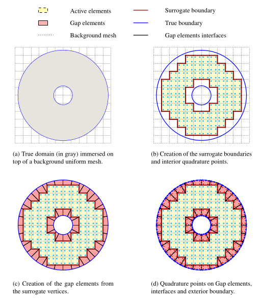
Figure 10. Visualization of the Gap-SBM for B-splines of order p = 1.
The numerical integration over the gap region is performed through curvilinear gap elements constructed by means of Coons patch parametrizations. The coons patch mapping F is defined as
where B0(), B1(), L0(), L1() are the lower, upper, left, and right boundary curves respectively, with , [0,1]. By construction the mapping interpolates exactly the four boundary curves as well as the corner points of the quadrilateral.
This choice is particularly natural because each gap element is bounded by three straight edges and one curved edge lying on the true boundary. The Coons construction provides a smooth transfinite interpolation of the element interior and allows standard Gaussian quadrature rules to be used on a reference domain. In practice, the true boundary is approximated locally by a polynomial curve of degree consistent with the spline discretization, so that the geometry of the gap elements remains compatible with the approximation order of the method. Figure 11 is useful here to show how the curvilinear parametrization evolves with the polynomial order.
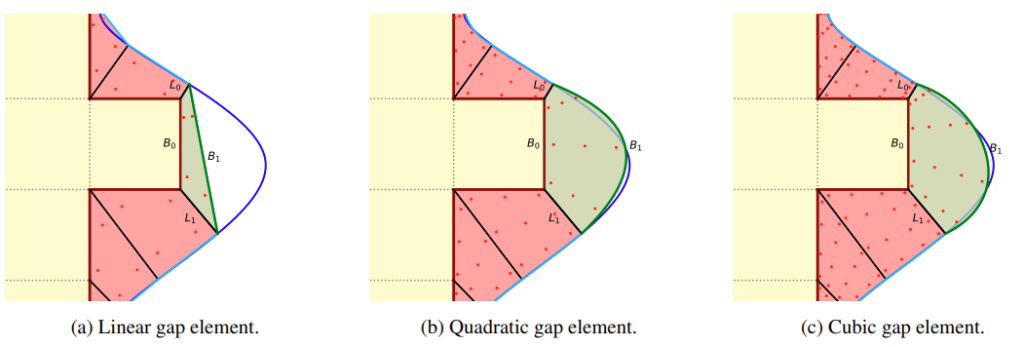
Figure 11. Coons patch parametrization and quadrature points for gap elements of increasing polynomial order.
Another important aspect of the method is that the treatment of the gap region and the treatment of the boundary conditions are conceptually separated. Once the computational domain has been reconstructed through the gap elements, boundary data can be imposed in different ways on the approximated boundary. In addition to direct imposition, the work investigates interpolation-based transfer from the true boundary and an SBM-type extrapolation from the reconstructed boundary to the exact one (see Figure 12). This separation is useful because it makes it possible to distinguish the effect of geometric approximation from the effect of boundary-data transfer, and therefore to understand more clearly where the remaining error comes from when the geometry is only approximated.
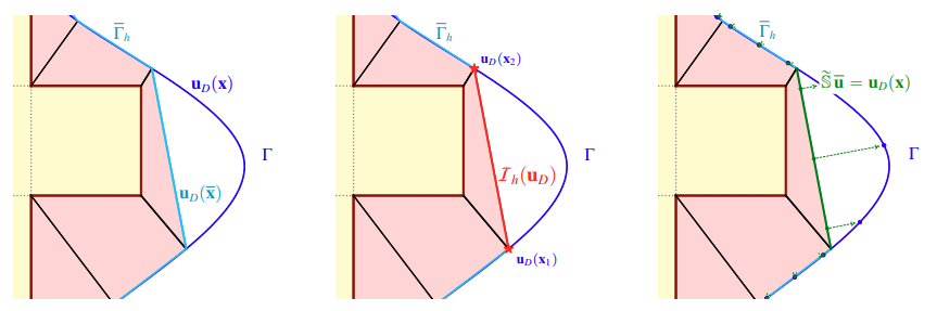
Figure 12. : Imposition of Dirichlet boundary conditions when the computational boundary does not coincide with the true boundary. From left to right: direct enforcement of the prescribed data on the approximated boundary; enforcement through interpolation of the boundary data sampled on the true boundary Γ; enforcement via the classical Shifted Boundary Method, in which the prescribed boundary data are transferred from Γ to the approximated boundary through the shift operator.
Numerical Results
The performance of the proposed Gap–SBM has been assessed through a set of numerical experiments designed to evaluate its accuracy, robustness, and computational properties. Particular attention has been devoted to three aspects that are especially relevant for the present work: the treatment of boundary conditions on curvilinear embedded geometries, the additional computational cost introduced by the gap reconstruction, and the conditioning of the resulting linear systems. Together, these tests provide a synthetic but representative picture of the method: on the one hand, they show that the Gap–SBM restores the accuracy lost by the classical SBM in the presence of Neumann boundary conditions; on the other hand, they confirm that this improvement is achieved without compromising the favorable numerical properties that make shifted-boundary approaches attractive in immersed settings.
The first relevant test is the curvilinear embedded benchmark defined by two concentric circles immersed in a square background domain, with Dirichlet conditions prescribed on the inner boundary and Neumann conditions on the outer one (Figure 10). This example is particularly useful because the geometry is not exactly represented by the computational domain, so that the results directly reflect both the quality of the gap reconstruction and the effect of the boundary-condition treatment. In this setting, the comparison between direct imposition, interpolation-based transfer, and SBM extrapolation shows that all Gap–SBM variants recover the expected asymptotic convergence rates and lead to a substantial improvement in both accuracy and robustness with respect to the classical SBM.
More specifically, the results in Figure 13 show that the influence of the boundary-data treatment depends on the polynomial degree. For linear discretizations, direct imposition already preserves the correct convergence rates, but interpolated boundary conditions and SBM extrapolation provide a visible gain in accuracy, with almost indistinguishable performance. For quadratic discretizations, the geometric approximation improves so rapidly that the differences between the three approaches become almost negligible. For cubic discretizations, the role of the boundary treatment becomes relevant again: while direct imposition remains asymptotically optimal, both interpolation and especially SBM extrapolation improve the solution accuracy at finer resolutions. In this sense, the benchmark highlights an important practical point: once the gap region is accurately reconstructed, the way boundary data are transferred to the approximated boundary can become the dominant factor controlling the final error.
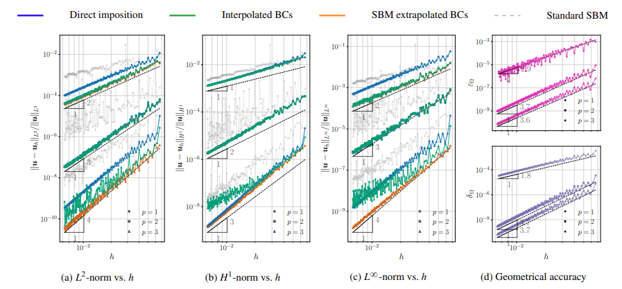
Figure 13. :Step-by-step convergence study for the concentric-circles benchmark with Dirichlet boundary conditions on the inner circle and Neumann boundary conditions on the outer circle (see Fig. 9). Panels (a)–(c) report the relative solution errors in the L 2 , H 1 , and L inf norms for different boundary-condition treatments. Panel (d) reports geometric error indicators of the surrogate domain.
The computational-cost analysis confirms that the improved accuracy of the Gap–SBM is obtained with a limited and well-controlled overhead. The timings are split into preprocessing, assembly, and solver stages (see Figure 14). The results show that the assembly cost grows approximately linearly with the number of degrees of freedom, whereas the linear solver cost grows superlinearly and rapidly becomes the dominant contribution under mesh refinement. By contrast, the additional overhead associated with the Gap–SBM construction follows a much milder growth, consistent with the theoretical estimate based on the number of cut surrogate edges. In practice, this means that the extra geometric work required to build and integrate the gap region does not become the dominant part of the simulation as the mesh is refined.
An important practical implication of these results is that the extra cost introduced by the Gap–SBM remains asymptotically of lower order than the cost of solving the linear system. Therefore, although the method requires a more elaborate preprocessing stage than the classical SBM, this additional effort is offset by the fact that the dominant computational burden still lies in the solver, exactly as in standard discretizations. It is also worth noting that, for very coarse linear meshes, the preprocessing stage may appear comparatively large; however, this should be interpreted with care, since both the surrogate-boundary construction and the generation of the gap elements follow a naturally parallelizable workflow. Overall, the timing results indicate that the method achieves a favorable balance between improved accuracy and computational overhead.
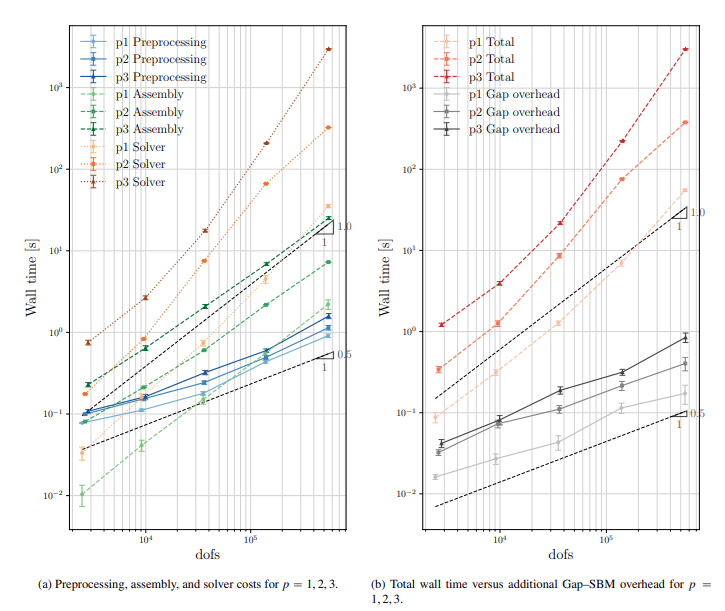
Figure 14. Computational cost analysis for the circular benchmark problem. The reported times are averaged over 20 repeated simulations.
The condition-number analysis of Figure 15 addresses one of the main motivations behind the Gap–SBM formulation, namely the preservation of robust linear-system behavior in an immersed high-order setting. The comparison with unstabilized cut-integration approaches is particularly informative. In the reported tests, the IBRA formulation without ghost-penalty stabilization exhibits the typical exponential growth of the condition number, together with large oscillations and extreme peaks. By contrast, both the classical SBM and the Gap–SBM display the expected algebraic growth proportional toh-2, confirming that the small cut-cell instability is avoided. Most importantly, the Gap–SBM shows an even smoother and more regular behavior than the classical SBM, with significantly reduced oscillations under mesh refinement.
This result is especially relevant because it shows that integrating over the geometric gap does not destroy the favorable conditioning mechanism inherited from SBM formulations. Even though the Gap–SBM introduces additional coupling terms through the gap contributions, no extra degrees of freedom are added, and all quantities are projected onto the already active basis functions. As a consequence, the stiffness matrix retains the conditioning properties expected from standard isogeometric discretizations. In practical terms, this makes the method much more attractive than cut-integration approaches for large-scale computations, since it supports the use of fast iterative solvers without requiring the additional stabilization machinery typically needed in unfitted methods based on trimmed cells.
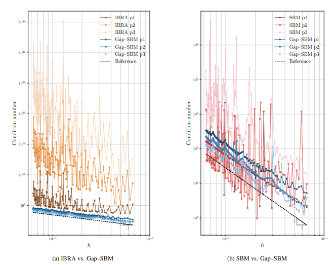
Figure 15. Condition number as a function of the mesh size for the circular geometry shown in Fig. 10
3.2 Three-dimensional Gap-SBM on complex STL geometries
A further development of the Gap-SBM concerns its extension to three-dimensional geometries described by triangulated surface data. This is an important step for the overall project, since many complex industrial or biomedical geometries are available as STL-type surface representations rather than as analysis-suitable volumetric spline parametrizations.
To assess this workflow, the Stanford Bunny was considered as a geometrically complex STL-derived benchmark. The input triangulated surface is embedded in a Cartesian spline background discretization, from which an internal surrogate domain is constructed by selecting the active background cells. The gap region between the surrogate boundary and the input surface is then reconstructed automatically, producing a computational domain that follows the external STL geometry without requiring a conforming body-fitted volume mesh. This construction is illustrated in Figure 16, where the original triangulated surface, a representative section of the surrogate boundary, and the reconstructed gap boundary are shown.
In this example, a linear geometric reconstruction of the three-dimensional gap cells was adopted. Although higher-order curved gap cells are possible in principle, they require tensor-product quadrature rules with a substantially larger number of integration points, leading to significant assembly and memory costs. The use of linear gap cells avoids this bottleneck and allows finer Cartesian discretizations to be considered. The remaining mismatch between the reconstructed and input boundaries is corrected through enhanced SBM extrapolation of order p.

Figure 16. Three-dimensional Gap-SBM reconstruction of the Stanford Bunny. The figure shows the input triangulated STL surface, a representative planar section of the Cartesian background discretization with the associated surrogate boundary, and the reconstructed gap boundary obtained through the three-dimensional gap construction.
The mechanical problem is defined by prescribing Dirichlet conditions on the lower support region of the Bunny and Neumann conditions on the remaining part of the surface. The prescribed boundary data are derived from a manufactured three-dimensional solution, so that the numerical error can be evaluated quantitatively. This setting makes it possible to test both the geometrical reconstruction and the accuracy of the shifted boundary treatment on a complex non-parametric surface.
For comparison, a conforming body-fitted finite element mesh was generated from the same STL surface using GiD. This mesh contained 372,516 nodes and 1,476,132 linear tetrahedral elements, corresponding to more than one million displacement degrees of freedom before the imposition of essential boundary conditions. The body-fitted mesh required extensive user-guided preprocessing, mesh generation, and quality control in order to avoid intersecting or excessively distorted elements. In contrast, the immersed Gap-SBM workflow preserved the input surface and generated a naturally refinable sequence of Cartesian discretizations without conforming volumetric remeshing.
The accuracy results in Figure 17 show a pronounced pre-asymptotic regime on coarse discretizations. This is expected, since the small-scale geometrical features of the Stanford Bunny are not sufficiently resolved when the distance between the surrogate and true boundaries is too large. However, once the relevant features are resolved, the Gap-SBM recovers the expected convergence behaviour in both the relative L2 and H1 norms. When the errors are plotted against the number of degrees of freedom, the expected three-dimensional rates are proportional to DOFs-(p+1)/3 in the L2 norm and DOFs-p/3 in the H1 norm.
The comparison with the standard SBM further confirms the benefit of explicitly reconstructing the missing gap region. For the Stanford Bunny benchmark, the standard SBM exhibits suboptimal convergence over the investigated refinement range, because the boundary shift alone does not adequately compensate for the geometrical mismatch associated with the smaller surface features. By integrating the region between the surrogate and true boundaries, and by correcting the residual boundary mismatch through enhanced extrapolation, the Gap-SBM progressively overcomes this limitation under refinement.
At the finest refinement levels, the linear Gap-SBM solution reaches errors comparable to those of the representative body-fitted finite element solution. The quadratic Gap-SBM discretization further reduces both the L2 and H1 errors while using considerably fewer degrees of freedom than the body-fitted FEM reference. This comparison should be interpreted at the workflow level rather than as a strict one-to-one comparison, since the body-fitted and immersed discretizations use different approximation orders and different spatial refinement distributions.
The computational-cost analysis confirms that the additional geometrical work introduced by the Gap-SBM remains controlled. The construction of the three-dimensional gap topology and geometry is localized near the surrogate boundary, and its ideal complexity scales with the number of boundary entities, namely approximately as O(DOFs2/3) under uniform refinement. The measured overhead grows slightly faster than this reference scaling, but remains of the same order of magnitude as the standard SBM geometry-construction cost. The total system assembly retains the expected approximately linear scaling with the number of degrees of freedom, although with a larger multiplicative constant for the Gap-SBM due to the additional gap-layer contributions.
Overall, the Stanford Bunny example demonstrates that the Gap-SBM can be used as a practical STL-to-analysis workflow for complex three-dimensional geometries. It avoids the need for an analysis-suitable body-fitted volume mesh, preserves the advantages of Cartesian spline discretizations, and recovers the expected convergence behaviour once the relevant geometrical features are sufficiently resolved. This result is particularly relevant for the subsequent contact developments, since it shows that the same gap-reconstruction strategy can support complex immersed geometries where body-fitted meshing would be costly or unreliable.
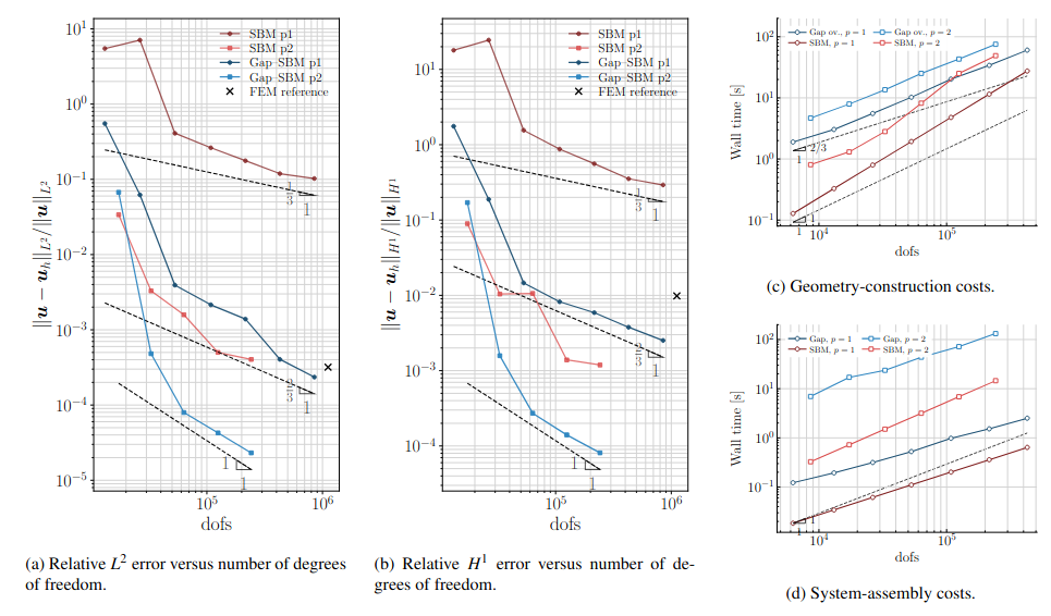
Figure 17. Accuracy and computational-cost analysis for the Stanford Bunny benchmark. The relative L2 and H1 errors are reported as functions of the number of degrees of freedom for standard SBM and Gap-SBM with spline degrees p=1 and p=2. The cost plots compare the geometry-construction overhead introduced by the Gap-SBM and the total system-assembly times. The results show that the Gap-SBM recovers the expected convergence behaviour on sufficiently refined discretizations while introducing a controlled additional computational cost.
- Gap-SBM multipatch coupling as an enabling tool for local refinement
The Gap-SBM framework was also extended to the coupling of independent isogeometric patches with non-matching discretizations. This development is important for the overall project because it provides a flexible way to introduce local refinement in immersed isogeometric simulations without requiring matching knot vectors, conforming parametrizations, or globally refined spline spaces.
In standard isogeometric analysis, local refinement can be difficult because tensor-product spline spaces tend to propagate refinement across large portions of the computational domain. This limitation is particularly relevant in structural and contact mechanics, where high resolution is often needed only in localized regions, such as stress concentrations, traction-loaded boundaries, or active contact zones. The Gap-SBM multipatch formulation addresses this issue by allowing different spline patches to be discretized independently and then weakly coupled through reconstructed gap regions.
The main idea is to treat the region between two non-matching patch interfaces in the same spirit as the Gap-SBM treatment of physical boundaries. Each patch retains its own approximation space, mesh size, polynomial degree, and parametrization. The geometrical region between the patch interfaces is reconstructed and used only for numerical integration. No additional degrees of freedom are introduced in the gap region, and the coupling conditions are imposed weakly through interface terms evaluated on the reconstructed geometry.
This construction makes it possible to introduce refined patches only where additional resolution is required, while retaining a coarser discretization elsewhere. In the first multipatch tests, this idea was applied to immersed boundary-value problems with Neumann conditions on an internal boundary. A locally refined patch was introduced around the immersed boundary and coupled to the surrounding coarser patch through the Gap-SBM multipatch formulation. The results showed that both local h-refinement and local p-refinement can improve the local accuracy near the immersed boundary without refining the complete computational domain.
Figure 18 illustrates this idea on an embedded Neumann problem. The single-patch configuration is compared with multipatch configurations in which either the mesh size or the polynomial degree is increased only in the patch surrounding the immersed boundary. The comparison shows that the multipatch setting can reduce the local error in the region where the boundary condition is imposed, while preserving a coarser discretization away from the critical region.
The relevance of this development became more evident in the subsequent immersed contact formulation. In contact mechanics, the pressure field and the associated stress gradients are typically localized around a small active contact region. The Gap-SBM multipatch framework therefore provides a natural way to concentrate the computational resolution near the contact interface. In the most recent contact developments, this idea was used to introduce localized h- and p-refinement near Hertzian and gear-pinion contact regions, while keeping the rest of the bodies more coarsely discretized.
Two refinement strategies were considered in the contact setting. The first is a boundary-oriented strategy, in which a fine patch is created along the physical boundary and coupled to a coarser interior patch. The second is a box-localized strategy, in which the fine background discretization is generated only inside a user-defined region surrounding the expected contact zone. The latter strategy further reduces the number of unnecessary fine cells away from contact and provides a more localized use of the high-resolution discretization.
Therefore, the Gap-SBM multipatch formulation should be interpreted as an enabling tool within the project. It connects the boundary-reconstruction capabilities of the Gap-SBM with the practical need for local refinement in immersed structural and contact simulations. Its role is not limited to the specific Poisson or elasticity benchmarks used for validation, but extends directly to the immersed contact framework discussed in the following section.
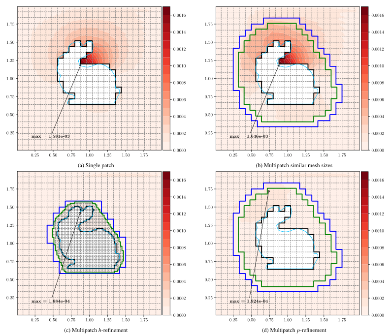
Figure 18. :Comparison of error distributions for an embedded Neumann boundary (pointwise absolute error). The black solid line represents the surrogate Neumann boundary. The blue line shows the outer patch’s surrogate inner boundary, and the green line shows the refined patch’s surrogate outer boundary (which coincides with the coupling interface). (a) Single-patch configuration using the classical SBM. (b) Two-patch configuration with similar mesh sizes. (c) Two-patch configuration with local ℎ-refinement around the Neumann boundary (inner patch mesh size reduced by a factor of 4). (d) Two-patch configuration with local 𝑝-refinement on the inner patch (cubic polynomial degree in inner patch, vs. quadratic in outer patch). (For interpretation of the references to colour in this figure legend, the reader is referred to the web version of this article.)
- Immersed isogeometric contact with SBM and Gap-SBM
The most recent development of the project concerns the extension of immersed contact mechanics to the high-order isogeometric setting [50]. The objective is to formulate frictionless contact between independently immersed elastic bodies, each described by its own background spline discretization, active domain, surrogate boundary, and physical contact surface. This setting is more complex than classical body-fitted contact, because the computational contact boundaries of the two bodies are generally non-matching and do not define a common interface, as shown in Fig. 19.
The formulation is developed in the small-deformation regime and considers homogeneous, isotropic, linear elastic materials. This restriction allows the geometrical and numerical aspects of the immersed contact formulation to be studied in a controlled setting, while retaining the main difficulties associated with independently immersed bodies, non-matching contact interfaces, surrogate geometries, and localized contact resolution.
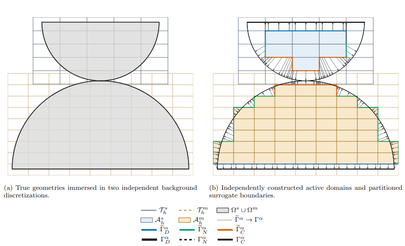
Figure 19. Geometrical construction for two independently immersed bodies. Each physical body is embedded in its own background discretization, from which the corresponding active domain and surrogate boundary are constructed independently. The surrogate boundaries are then partitioned into Dirichlet, Neumann, and candidate contact portions according to the corresponding surrogate-to-physical projections.
For two deformable bodies, denoted as slave and master, the contact kinematics are described through the normal gap between the two physical contact surfaces. Following the standard master–slave convention, the slave side is selected as the reference and integration side, while the master body provides the target surface for the contact projection. The small-displacement normal gap can be written as

where gN,0 is the initial geometrical gap, n is the slave-side normal direction, and [[u]]denotes the displacement jump between the two bodies. The frictionless contact conditions are expressed through the standard complementarity relations

where pN is the normal contact pressure. These conditions enforce non-penetration, non-adhesion, and complementarity between the normal gap and the contact pressure.
Since each body is immersed independently, the slave and master surrogate contact boundaries do not generally coincide with each other or with the physical contact boundaries. Therefore, a contact association must be constructed through a sequence of geometrical maps. A point on the slave surrogate contact boundary is first projected onto the physical slave contact boundary. From there, a slave-normal projection identifies the corresponding point on the physical master contact boundary. Finally, this physical master point is associated with the master surrogate boundary. In compact form, this composition can be written as

This mapping defines the contact pair on the physical surfaces, while the discrete fields remain associated with the independently constructed surrogate spline discretizations (see Figure 20).
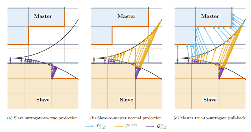
Figure 20. Construction of the one-pass surrogate contact association. A point on the slave surrogate contact boundary is first mapped to the physical slave boundary, then projected onto the physical master boundary along the slave normal, and finally related to the master surrogate boundary. The composition of these maps defines the contact association between the independently immersed bodies.
This construction is one of the main differences with respect to standard body-fitted contact. In the body-fitted case, the contact interface is directly represented by the computational boundaries. In the immersed case, the contact quantities must be transferred consistently between surrogate and physical geometries. The formulation must therefore account for different normals, different integration measures, and non-matching discretization breakpoints on the two contacting sides.
To handle the non-matching character of the contact interface, a mortar-type segmentation is introduced on the slave side. The endpoints of the master contact segments are pulled back onto the slave integration boundary and combined with the native slave segment boundaries. The resulting partition defines integration subsegments over which the corresponding slave and master element pair remains fixed. This provides a consistent segment-wise quadrature of the non-matching contact interface. In this work, the term mortar refers to the construction of the integration partition, while the contact constraint itself is enforced through Nitsche’s method.
The unilateral contact constraint is imposed through a biased one-pass Nitsche formulation. The projected contact operator combines the slave-side normal traction with a stabilization term proportional to the normal gap,

where tN,hs is the slave-side normal traction, gN,h is the discrete normal gap, and N is the Nitsche stabilization parameter. The negative part of this operator is used to activate the contact contribution only where the unilateral constraint is violated. This makes it possible to treat the transition between active and inactive contact regions without introducing additional Lagrange multiplier unknowns.
In the SBM contact formulation, contact integration is performed on the slave surrogate contact boundary. The normal gap is evaluated at the associated physical contact pair through shifted displacement fields, while the contact traction is obtained from the shifted slave-side stress. The residual contribution is then assembled on the surrogate boundary, using a projected integration measure that accounts for the relative orientation between the physical and surrogate slave boundaries. In this way, the SBM formulation preserves the cut-cell-free character of the shifted boundary framework.
In the Gap-SBM contact formulation, Fig. 21, the same Nitsche enforcement and the same slave-side segmentation strategy are used, but the geometrical treatment of the contact interface is different. The regions between the surrogate and physical boundaries are reconstructed through integration-only gap cells. The spline fields are extended into these reconstructed regions, and the contact quantities are evaluated directly on the reconstructed physical contact geometry. The contact contribution is therefore integrated with the physical measure on the reconstructed interface, rather than on the surrogate boundary.
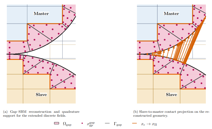
Figure 21. Local geometric construction used in the Gap-SBM contact formulation. The reconstructed gap regions provide the quadrature support for the extended discrete fields, while the slave-to-master contact projection is defined directly on the reconstructed physical contact geometry.
The comparison between SBM and Gap-SBM is meaningful because the contact enforcement is kept the same in both formulations. The difference lies in the geometrical representation of the contact interface and in the evaluation of the contact quantities. In the SBM formulation, the physical quantities are recovered through shifted operators and assembled on the surrogate boundary. In the Gap-SBM formulation, the physical contact interface is reconstructed and the extended fields are evaluated directly on it. This makes it possible to isolate the influence of the geometrical treatment of the immersed contact interface.
The resulting framework can therefore be interpreted as a unified immersed isogeometric contact formulation in which two different geometrical treatments are compared under the same biased one-pass Nitsche strategy. The SBM provides a simpler surrogate-boundary formulation, while the Gap-SBM provides a reconstructed-interface formulation that is particularly useful when the complete physical contact boundary must be recovered accurately. This distinction becomes especially important in the numerical examples involving immersed corners, boundary-condition transitions, and localized contact regions.
- Numerical results of the immersed isogeometric contact framework
The immersed isogeometric contact framework was assessed through a sequence of numerical tests of increasing complexity. The objective was not only to verify the accuracy of the proposed contact formulation, but also to understand the effect of the geometrical treatment of the contact interface, the role of local refinement, and the applicability of the method to more representative contact configurations.
The results reported here focus on four representative cases. First, contact patch tests are used to isolate the consistency of the formulation and the effect of immersed contact corners. Second, a Hertzian cylinder–cylinder benchmark provides a quantitative comparison with an analytical contact-pressure distribution. Third, local multipatch refinement is assessed on the same Hertzian benchmark in order to evaluate whether the contact response can be recovered without uniformly refining the complete bodies. Finally, a gear–pinion contact problem is considered as a more complex application involving curved contact surfaces, localized stress concentrations, and contact-region migration.
Contact patch test: effect of the immersed geometry
The first set of tests concerns two-body contact patch tests. These examples are useful because the exact solution corresponds to a uniform stress state transmitted across the contact interface. They therefore make it possible to distinguish errors caused by the contact enforcement itself from errors caused by the immersed geometrical representation.
In the equal-size rectangular patch test, both the SBM and Gap-SBM formulations reproduce the analytical compression state up to numerical precision. This confirms that the biased one-pass Nitsche formulation and the mortar-type segmentation are consistent when the contact interface is not affected by geometrical coverage issues.
A more demanding test is obtained by rotating the complete two-body configuration with respect to the Cartesian background discretizations. In this case, all boundaries are immersed and the contact boundary meets other boundary-condition portions at non-smooth immersed corners. The standard SBM exhibits localized stress errors near the contact corners. These errors are not caused by the Nitsche contact formulation itself, but by the fact that the surrogate-to-true boundary mapping does not cover the complete physical contact interface close to the corners.
The Gap-SBM avoids this limitation by reconstructing the region between the surrogate and true boundaries and by integrating up to the complete physical contact interface. As a result, the uniform patch state is recovered up to machine precision, while the standard SBM only approaches the exact state under mesh refinement. This test clearly shows the main geometrical advantage of the Gap-SBM contact formulation: when the complete physical interface must be represented accurately, reconstruction of the gap region is more robust than relying only on shifted quantities from the surrogate boundary. The paper reports this distinction clearly in the rotated patch test, where Gap-SBM recovers the complete contact interface and the SBM error remains localized near contact corners, as shown in Figure 22 .
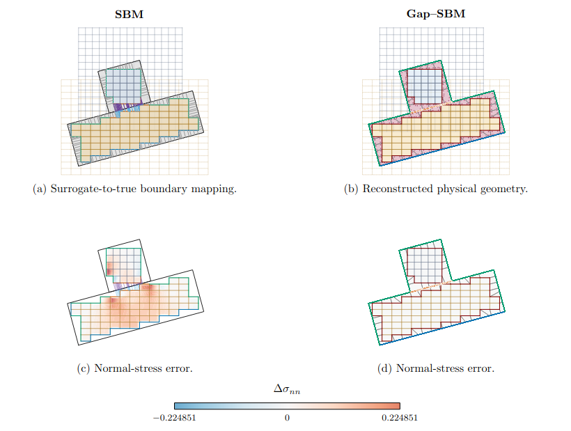
Figure 22. Fully immersed rotated contact patch test. The SBM formulation exhibits localized stress errors near the contact corners because the surrogate-to-true mapping does not cover the complete physical contact interface. The Gap-SBM reconstruction recovers the complete physical boundary and reproduces the uniform stress state up to numerical precision.
Hertzian cylinder–cylinder contact
The second benchmark is the Hertzian cylinder–cylinder contact problem. This test provides a quantitative reference for the normal contact-pressure distribution and is used to compare the SBM and Gap-SBM formulations under uniform mesh refinement. The same one-pass Nitsche enforcement, mortar segmentation, material parameters, and background discretizations are used for both formulations, so that the comparison isolates the effect of the geometrical treatment of the contact interface.
Both immersed formulations progressively recover the analytical Hertzian pressure profile under refinement. The largest discrepancies are concentrated near the edges of the active contact region, where the analytical pressure exhibits the characteristic square-root decay. This non-smooth behaviour limits the benefit of increasing the polynomial degree and makes the observed convergence rates sensitive to the error measure and to the active contact extent.
The results show that quadratic spline discretizations improve the representation of the central pressure distribution and the maximum pressure for both SBM and Gap-SBM. At the finest common local mesh resolution, the relative pressure error is reduced from approximately eight percent for linear discretizations to approximately four percent for quadratic discretizations. The error in the maximum contact pressure falls below one percent for the quadratic cases. The predicted contact half-width is less sensitive to the polynomial degree, reflecting the difficulty of accurately locating the transition between active and inactive contact.
For this smooth Hertzian configuration, the SBM and Gap-SBM contact treatments show comparable behaviour when the contact region is sufficiently resolved (see Figure 23). This indicates that, when the physical interface is smooth and well covered by the surrogate-to-true mapping, the simpler SBM formulation can provide contact pressures close to those obtained with the reconstructed Gap-SBM interface. The advantage of the Gap-SBM becomes more evident in geometrically more difficult configurations, such as immersed contact corners or non-smooth boundary-condition transitions. The paper reports this close behaviour for the Hertz benchmark, with both formulations recovering the Hertz pressure distribution and quadratic discretizations reducing the peak-pressure error below one percent.
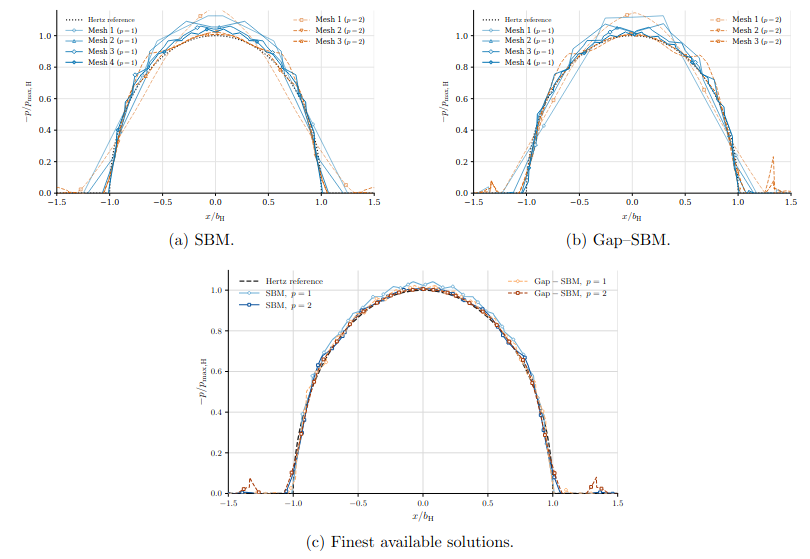
Figure 23. Normalized contact-pressure distributions for the Hertzian cylinder–cylinder benchmark. The SBM and Gap-SBM formulations are compared with the analytical Hertz solution for linear and quadratic spline discretizations. Both methods recover the Hertzian pressure profile under mesh refinement, with improved peak-pressure prediction for quadratic splines.
Local multipatch refinement for contact
The Hertzian benchmark was also used to assess local multipatch refinement. This part is important because contact pressures and stress gradients are strongly localized near the active contact region. A uniformly fine discretization of the complete bodies is therefore inefficient, especially when high-order spline spaces are used.
Three refinement strategies were compared: uniform refinement, boundary-oriented multipatch refinement, and box-localized refinement. In the multipatch cases, a fine patch is introduced near the contact region and coupled to a coarser surrounding patch through the Gap-SBM multipatch formulation. The same local resolution is retained in the contact region, while the rest of the body is represented with a coarser discretization.
The results show that the local contact response is mainly controlled by the resolution available in the active contact region. Uniform refinement, boundary-oriented multipatch refinement, and box-localized refinement produce very similar local stress distributions and contact-pressure profiles when the contact-zone resolution is comparable. This confirms that the fine discretization does not need to extend throughout the complete bodies in order to recover the local Hertzian response.
The efficiency advantage becomes clear when the pressure error is plotted against the total number of degrees of freedom, as in Figure 24. The multipatch strategies reach a comparable level of contact-pressure accuracy with fewer global unknowns than uniform refinement, because the fine resolution is concentrated only where it is mechanically needed. The box-localized strategy is the most localized option, since it restricts the refined discretization to a prescribed region around the contact zone. The paper explicitly reports that the three strategies have similar behaviour when plotted against local mesh size, while the multipatch strategies become more efficient when plotted against global degrees of freedom.
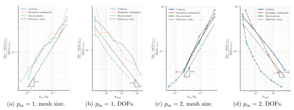
Figure 24. Convergence and degree-of-freedom efficiency of the local refinement strategies for the Gap-SBM contact formulation. Uniform refinement, boundary-oriented multipatch refinement, and box-localized refinement are compared in terms of contact-pressure error versus local mesh size and total number of degrees of freedom. The multipatch strategies preserve the local contact accuracy while reducing the number of global unknowns required to reach a comparable error level.
Gear–pinion contact benchmark
The final benchmark is a gear–pinion contact problem. This example is more representative than the Hertzian cylinder–cylinder benchmark because the contacting tooth flanks have continuously varying curvature, the contact region may migrate under load, and the stress field is strongly localized near the active tooth pair and the tooth roots.
The immersed SBM and Gap-SBM solutions were compared with an independent body-fitted finite element simulation performed in Kratos using a frictionless Augmented Lagrangian contact formulation. The body-fitted solution was used as a numerical reference rather than as an exact solution. The immersed discretizations employed local multipatch refinement near the selected contact region, while the remaining parts of the bodies were represented more coarsely.
The comparison of the local normal-stress fields showed that the body-fitted FEM, SBM, and Gap-SBM formulations capture the same main contact response. To interpret the pressure profiles, two Hertzian estimates were considered. The first one was constructed at the initial tangency point of the tooth flanks. The second one was updated using the effective contact location identified from the refined FEM solution. This updated estimate accounts for the migration of the contact region along the original tooth profiles.
The pressure profiles at three torque levels show close agreement between FEM, SBM, Gap-SBM, and the updated local Hertzian estimate, Fig. 25. The initial Hertzian estimate is shifted with respect to the numerical contact region, while the updated estimate captures both the pressure peak and the contact width much more accurately. At the nominal load, the numerical pressure profiles show a slight asymmetry, which is consistent with the fact that a wider portion of the tooth flank is involved and the local curvature varies across the active contact region.
This example demonstrates that the proposed immersed isogeometric contact framework can be applied to a geometrically complex mechanical configuration. The agreement with the body-fitted FEM solution and with the updated Hertzian estimate indicates that the local contact response can be captured accurately while retaining the flexibility of immersed discretizations and localized multipatch refinement. The paper reports that FEM, SBM, and Gap-SBM remain close across the three load levels, and that the updated Hertzian estimate reproduces the contact width and peak pressure well.
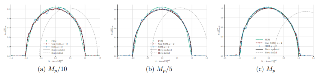
Figure 25. Normal contact-pressure profiles for the gear–pinion benchmark at three applied torque levels. Body-fitted FEM, SBM, and Gap-SBM solutions are compared with two Hertzian estimates: one based on the initial tangency point and one updated using the effective contact location obtained from the refined FEM solution. The updated estimate captures the contact location, width, and peak pressure more accurately, while the numerical solutions remain close across the three load levels.
- Conclusions and Outlook
This report summarized the progress of the PhD project on immersed and high-order computational mechanics based on the Shifted Boundary Method, the Gap-Shifted Boundary Method, and Isogeometric Analysis. The work has evolved from the initial integration of SBM within IGA toward a broader framework for structural and contact mechanics on complex geometries.
The first stage of the project focused on the development of SBM–IGA as a cut-cell-free strategy for embedded geometries. The method combines the accuracy and smoothness of spline-based discretizations with the flexibility of immersed methods, avoiding body-fitted mesh generation and small cut-cell instabilities. The numerical results showed good agreement with body-fitted IGA for Dirichlet-dominated problems, while also revealing the main limitation of the classical SBM: a reduced accuracy and stronger sensitivity for Neumann and traction boundary conditions.
A first extension toward contact mechanics was then developed in the finite element setting. This work showed that frictionless contact conditions can be imposed on surrogate contact surfaces by shifting the relevant kinematic and mechanical quantities from the true boundary to the surrogate one. The Hertzian contact benchmarks confirmed that the SBM can reproduce analytical and body-fitted contact-pressure distributions with good accuracy, while avoiding cut-cell integration. This represented an important intermediate step toward high-order immersed contact formulations.
The central methodological contribution of the project was the development of the Gap-SBM in the isogeometric framework. By reconstructing the region between the surrogate and true boundaries through integration-only gap elements, the method recovers the missing contribution of the physical domain without adding degrees of freedom. The numerical results showed improved accuracy for Neumann and traction boundary conditions, reduced sensitivity to the surrogate boundary, and favourable conditioning behaviour.
The Gap-SBM was also extended toward more general workflows. The three-dimensional Stanford Bunny benchmark demonstrated its potential as an STL-to-analysis strategy for complex triangulated geometries, avoiding the need for analysis-suitable body-fitted volume meshes. In parallel, the Gap-SBM multipatch formulation provided a flexible way to couple independent spline patches with different mesh sizes, polynomial degrees, and parametrizations. This makes it possible to introduce local h- and p-refinement near immersed boundaries or regions of interest without uniformly refining the complete domain.
The most recent stage of the project combined these developments in an immersed isogeometric contact framework based on SBM and Gap-SBM. The formulation considers frictionless contact between independently immersed elastic bodies and uses a biased one-pass Nitsche strategy with mortar-type segmentation. Since the SBM and Gap-SBM contact formulations share the same enforcement strategy, their comparison isolates the effect of the geometrical treatment of the contact interface.
The numerical results showed that both formulations can reproduce Hertzian contact responses when the interface is smooth and sufficiently resolved. The Gap-SBM, however, provides a clear advantage in fully immersed configurations with contact corners and boundary-condition transitions, where the classical SBM may fail to cover the complete physical contact interface. The local multipatch refinement studies further showed that accurate contact pressures can be obtained by refining only the active contact region, reducing the need for globally fine discretizations.
Finally, the gear–pinion benchmark demonstrated the applicability of the framework to a more complex mechanical configuration involving curved contact surfaces, localized stress concentrations, and contact-region migration. The immersed SBM and Gap-SBM solutions showed close agreement with body-fitted finite element results and with an updated local Hertzian estimate, confirming the potential of the approach for geometrically complex contact problems.
Overall, the project has progressed from a first SBM–IGA proof of concept to a more complete immersed isogeometric framework combining accurate boundary treatment, local refinement, and contact mechanics. Future work will focus on three-dimensional contact, improved automation for complex industrial geometries, and the extension to nonlinear material behaviour, especially elastoplasticity.
- REFERENCES
- Thomas J.R. Hughes, John A. Cottrell, Yuri Bazilevs, Isogeometric analysis: CAD, finite elements, NURBS, exact geometry and mesh refinement, Comput. Methods Appl. Mech. Engrg. 194 (39) (2005) 4135–4195.
- John A. Cottrell, Alessandro Reali, Yuri Bazilevs, Thomas J.R. Hughes, Isogeometric analysis of structural vibrations, Comput. Methods Appl. Mech. Engrg. 195 (41) (2006) 5257–5296.
- Yuri Bazilevs, Lourenco Beirao da Veiga, John A. Cottrell, Thomas J.R. Hughes, Giancarlo Sangalli, Isogeometric analysis: Approximation, stability and error estimates for h-refined meshes, Math. Models Methods Appl. Sci. 16 (07) (2006) 1031–1090.
- Yuri Bazilevs, Victor M. Calo, Yongjie Zhang, Thomas J.R. Hughes, Isogeometric fluid–structure interaction analysis with applications to arterial blood flow, Comput. Mech. 38 (4) (2006) 310–322.
- Yongjie Zhang, Yuri Bazilevs, Samrat Goswami, Chandrajit L. Bajaj, Thomas J.R. Hughes, Patient-specific vascular NURBS modeling for isogeometric analysis of blood flow, Comput. Methods Appl. Mech. Engrg. 196 (29) (2007) 2943–2959.
- John A. Cottrell, Thomas J.R. Hughes, Alessandro Reali, Studies of refinement and continuity in isogeometric structural analysis, Comput. Methods Appl. Mech. Engrg. 196 (41) (2007) 4160–4183.
- Josef Kiendl, Kai-Uwe Bletzinger, Johannes Linhard, Roland Wüchner, Isogeometric shell analysis with Kirchhoff–Love elements, Comput. Methods Appl. Mech. Engrg. 198 (49) (2009) 3902–3914.
- David J. Benson, Yuri Bazilevs, Ming-Chen Hsu, Thomas J.R. Hughes, Isogeometric shell analysis: The Reissner–Mindlin shell, Comput. Methods Appl. Mech. Engrg. 199 (5) (2010) 276–289, Computational Geometry and Analysis.
- Kenji Takizawa, Yuri Bazilevs, Tayfun E. Tezduyar, Ming-Chen Hsu, Takuya Terahara, Computational cardiovascular medicine with isogeometric analysis, J. Adv. Eng. Comput. 6 (3) (2022) 167–199.
- Massimo Carraturo, Carlotta Giannelli, Alessandro Reali, Rafael Vázquez, Suitably graded THB-spline refinement and coarsening: Towards an adaptive isogeometric analysis of additive manufacturing processes, Comput. Methods Appl. Mech. Engrg. 348 (2019) 660–679.
- Carlotta Giannelli, Bert Jüttler, Hendrik Speleers, THB-splines: The truncated basis for hierarchical splines, Comput. Aided Geom. Design 29 (7) (2012) 485–498, Geometric Modeling and Processing 2012.
- Dominik Schillinger, Luca Dedè, Michael A. Scott, John A. Evans, Michael J. Borden, Ernst Rank, Thomas J.R. Hughes, An isogeometric design-through-analysis methodology based on adaptive hierarchical refinement of NURBS, immersed boundary methods, and T-spline CAD surfaces, Comput. Methods Appl. Mech. Engrg. 249–252 (2012) 116–150, Higher Order Finite Element and Isogeometric Methods.
- Martin Ruess, Dominik Schillinger, Yuri Bazilevs, Vasco Varduhn, Ernst Rank, Weakly enforced essential boundary conditions for NURBS-embedded and trimmed NURBS geometries on the basis of the finite cell method, Internat. J. Numer. Methods Engrg. 95 (10) (2013) 811–846.
- Jamshid Parvizian, Alexander Düster, Ernst Rank, Finite cell method: h-and p-extension for embedded domain problems in solid mechanics, Comput. Mech. 41 (1) (2007) 121–133.
- Ernst Rank, Martin Ruess, Stefan Kollmannsberger, Dominik Schillinger, Alexander Düster, Geometric modeling, isogeometric analysis and the finite cell method, Comput. Methods Appl. Mech. Engrg. 249–252 (2012) 104–115.
- Michael Breitenberger, Andreas Apostolatos, Philipp Bucher, Roland Wüchner, Kai-Uwe Bletzinger, Analysis in computer aided design: Nonlinear isogeometric B-Rep analysis of shell structures, Comput. Methods Appl. Mech. Engrg. 284 (2015) 401–457, Isogeometric Analysis Special Issue.
- Tobias Teschemacher, Anna M. Bauer, Thomas Oberbichler, Micheal Breitenberger, Riccardo Rossi, Roland Wüchner, Kai-Uwe Bletzinger, Realization of CAD-integrated shell simulation based on isogeometric B-Rep analysis, Adv. Model. Simul. Eng. Sci. 5 (2018) 1–54.
- Tobias Teschemacher, Anna M. Bauer, Ricky Aristio, Manuel Meßmer, Roland Wüchner, Kai-Uwe Bletzinger, Concepts of data collection for the CAD-integrated isogeometric analysis, Eng. Comput. 38 (6) (2022) 5675–5693.
- Manuel Meßmer, Tobias Teschemacher, Lukas F. Leidinger, Roland Wüchner, Kai-Uwe Bletzinger, Efficient CAD-integrated isogeometric analysis of trimmed solids, Comput. Methods Appl. Mech. Engrg. 400 (2022) 115584.
- Manuel Meßmer, Stefan Kollmannsberger, Roland Wüchner, Kai-Uwe Bletzinger, Robust numerical integration of embedded solids described in boundary representation, Comput. Methods Appl. Mech. Engrg. 419 (2024) 116670.
- Erik Burman, Ghost penalty, C. R. Math. 348 (21–22) (2010) 1217–1220.
- Santiago Badia, Eric Neiva, Francesc Verdugo, Linking ghost penalty and aggregated unfitted methods, Comput. Methods Appl. Mech. Engrg. 388 (2022) 114232.
- Alex Main, Guglielmo Scovazzi, The shifted boundary method for embedded domain computations. Part I: Poisson and Stokes problems, J. Comput. Phys. 372 (2018) 972–995.
- Alex Main, Guglielmo Scovazzi, The shifted boundary method for embedded domain computations. Part II: Linear advection–diffusion and incompressible Navier–Stokes equations, J. Comput. Phys. 372 (2018) 996–1026.
- Nabil M. Atallah, Guglielmo Scovazzi, Nonlinear elasticity with the shifted boundary method, Comput. Methods Appl. Mech. Engrg. 426 (2024) 116988.
- Efthymios N. Karatzas, Giovanni Stabile, Leo Nouveau, Guglielmo Scovazzi, Gianluigi Rozza, A reduced-order shifted boundary method for parametrized incompressible Navier–Stokes equations, Comput. Methods Appl. Mech. Engrg. 370 (2020) 113273.
- Nabil M. Atallah, Claudio Canuto, Guglielmo Scovazzi, The second-generation shifted boundary method and its numerical analysis, Comput. Methods Appl. Mech. Engrg. 372 (2020) 113341.
- Nabil M. Atallah, Claudio Canuto, Guglielmo Scovazzi, Analysis of the shifted boundary method for the Poisson problem in domains with corners, Math. Comp. 90 (331) (2021) 2041–2069.
- Antonelli, N., Aristio, R., Gorgi, A., Zorrilla, R., Rossi, R., Scovazzi, G., & Wüchner, R. (2024). The Shifted Boundary Method in Isogeometric Analysis. Computer Methods in Applied Mechanics and Engineering, 430, 117228.
- Hertz, Heinrich. “The contact of elastic solids.” J Reine Angew, Math 92 (1881): 156-171.
- Johnson, Kenneth Langstreth. Contact mechanics. Cambridge university press, 1987.
- Jackson, R. L., & Green, I. (2003, January). A finite element study of elasto-plastic hemispherical contact. In International Joint Tribology Conference (Vol. 37068, pp. 65-72).
- Barber, J. R., & Ciavarella, M. (2000). Contact mechanics. International Journal of solids and structures, 37(1-2), 29-43.
- Wriggers, Peter. Computational contact mechanics. Ed. Tod A. Laursen. Vol. 2. Berlin: Springer, 2006.
- Kogut, L., & Etsion, I. (2002). Elastic-plastic contact analysis of a sphere and a rigid flat. J. Appl. Mech., 69(5), 657-662.
- Cottrell, J. A., Hughes, T. J., & Bazilevs, Y. (2009). Isogeometric analysis: toward integration of CAD and FEA. John Wiley & Sons.
- Temizer, I., Wriggers, P., & Hughes, T. (2011). Contact treatment in isogeometric analysis with NURBS. Computer Methods in Applied Mechanics and Engineering, 200(9-12), 1100-1112.
- De Lorenzis, L., Temizer, İ., Wriggers, P., & Zavarise, G. (2011). A large deformation frictional contact formulation using NURBS‐based isogeometric analysis. International Journal for Numerical Methods in Engineering, 87(13), 1278-1300.
- Alart, P., & Curnier, A. (1991). A mixed formulation for frictional contact problems prone to Newton like solution methods. Computer methods in applied mechanics and engineering, 92(3), 353-375.
- Kim, J. Y., & Youn, S. K. (2012). Isogeometric contact analysis using mortar method. International Journal for Numerical Methods in Engineering, 89(12), 1559-1581.
- Dimitri, R., De Lorenzis, L., Scott, M. A., Wriggers, P., Taylor, R. L., & Zavarise, G. (2014). Isogeometric large deformation frictionless contact using T-splines. Computer methods in applied mechanics and engineering, 269, 394-414.
- Puso, M. A., & Laursen, T. A. (2004). A mortar segment-to-segment frictional contact method for large deformations. Computer methods in applied mechanics and engineering, 193(45-47), 4891-4913.
- Temizer, I., & Hesch, C. (2016). Hierarchical NURBS in frictionless contact. Computer Methods in Applied Mechanics and Engineering, 299, 161-186.
- Dimitri, R. (2015). Isogeometric treatment of large deformation contact and debonding problems with T-splines: a review. Curved and Layered Structures, 2(1).
- Atallah, N. M., Canuto, C., & Scovazzi, G. (2021). The shifted boundary method for solid mechanics. International Journal for Numerical Methods in Engineering, 122(20), 5935-5970.
- Main, A., & Scovazzi, G. (2018). The shifted boundary method for embedded domain computations. Part II: Linear advection–diffusion and incompressible Navier–Stokes equations. Journal of Computational Physics, 372, 996-1026.
- Li, Kangan, et al. “The shifted boundary method for contact problems.” Computer Methods in Applied Mechanics and Engineering 440 (2025): 117940.
- Popp, Alexander, Michael W. Gee, and Wolfgang A. Wall. “A finite deformation mortar contact formulation using a primal–dual active set strategy.” International Journal for Numerical Methods in Engineering 79.11 (2009): 1354-1391.
- Gorgi, A., Cornejo, A., Scovazzi, G., Rossi, R. The Isogeometric Gap-Shifted Boundary Method. Computer Methods in Applied Mechanics and Engineering, 462, 119293, 2026.
- Antonelli, Nicolò, et al. “Isogeometric multipatch coupling with arbitrary refinement and parametrization using the Gap–Shifted Boundary Method.” Computer Methods in Applied Mechanics and Engineering 456 (2026): 118913.
- Gorgi, A., et al. Immersed Isogeometric Contact with SBM and Gap-SBM: Nitsche Formulations and Local Multipatch Refinement. (submitted)
Leave a Reply
Want to join the discussion?Feel free to contribute!